Understanding Z-Transformations for Digital Control Systems
Written on
Chapter 1: Introduction to Z-Transformations
The emergence of digital computers in the 1950s enabled control engineers to implement advanced control systems, leading to the Z-transform becoming a vital tool for the analysis and design of these systems. The Z-transform is a mathematical framework that transforms a discrete-time signal—sampled at distinct intervals—into a complex function associated with a variable known as the Z-transform variable. This transformation allows for the examination of a discrete-time system's behavior in the frequency domain, which is crucial for developing digital filters, controllers, and a variety of digital signal processing systems.

Section 1.1: Various Approaches to Z-Transform
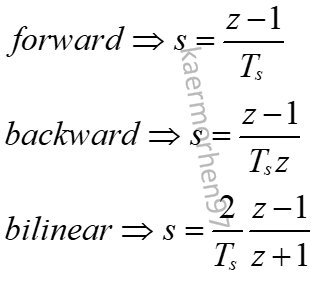
The Z-transform encompasses several methodologies, namely the forward, backward, and bilinear Z-transforms. Below is a breakdown of each approach:
Subsection 1.1.1: Forward Z-Transform
The forward Z-transform, also referred to as the unilateral Z-transform (or the first-order Euler approximation), converts a sequence of time-domain values into the Z-domain. This is achieved by summing the product of each value in the sequence and Z raised to the power corresponding to the sample number, starting from zero.
Subsection 1.1.2: Backward Z-Transform
Known as the inverse Z-transform (or the second-order Euler approximation), the backward Z-transform converts a Z-domain function back into a sequence of time-domain values. It essentially serves as the reverse process of the forward Z-transform.
Subsection 1.1.3: Bilinear Z-Transform
The bilinear Z-transform is a technique for transitioning a continuous-time system into a discrete-time one. Commonly called the Tustin method or Trapezoidal integration, it maps the s-plane (from the Laplace transform domain) onto the z-plane (from the Z-transform domain) through a bilinear transformation.
Chapter 2: Practical Example of Z-Transformations
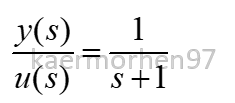
To illustrate these concepts, consider the following transfer function in Laplace form:
In this example:
- (y) represents the output
- (u) denotes the input
- (s) signifies the Laplace form
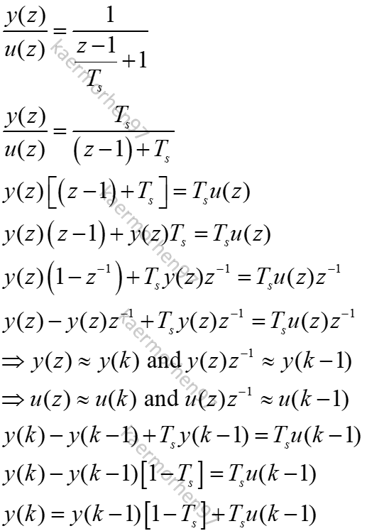
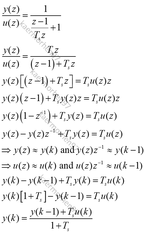
The three approaches can be applied as follows:
Forward Transformation:
Backward Transformation:
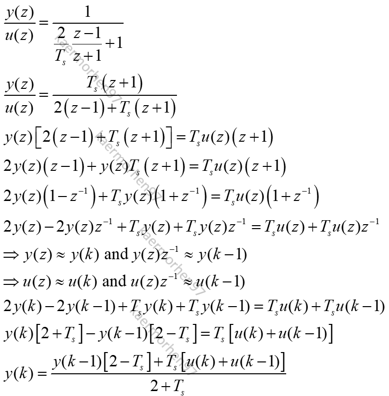
Bilinear Transformation:
Further Reading
For a more comprehensive understanding of these concepts, refer to K. Ogata's "Discrete-Time Control Systems," published by Prentice-Hall in 1995.
Note: If you notice any inaccuracies in this article, please feel free to share your thoughts in the comments. Constructive feedback is always appreciated!
This video, titled "Digital Control 3: The Z-transform," provides an in-depth look at Z-transformations, offering valuable insights into their applications in control systems.
The second video, "Discrete Control Systems Fundamentals: Overview of Z Transforms," serves as a foundational overview of the Z-transform and its significance in discrete control systems.